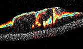

Magnetomotive Ultrasound (MMUS) System: The magnetomotive ultrasound (MMUS) system, pictured in Figure 1 is designed to image areas in tissue or tissue models that have been infused with iron oxide particles. Built around a commercially-available Ultrasonix SonixTouch ultrasound platform with a L14-5/38 linear transducer, the system employs two electromagnets to create a sinusoidal magnetic gradient force in the imaging area. The force causes the portions of the imaging area with iron oxide particles (which are highly-paramagnetic) to oscillate up and down, with a frequency and acoustic phase that matches the magnets’ frequency and phase. Ultrasound RF data is collected for 7.5 seconds, and sent to a computer for analysis. This analysis determines which portions of the image are being displaced at the magnet frequency and phase. For more on how magnetomotive imaging works, see our Magnetomotive Imaging page. For more on the design of this MMUS system see Pope et al, 2013.
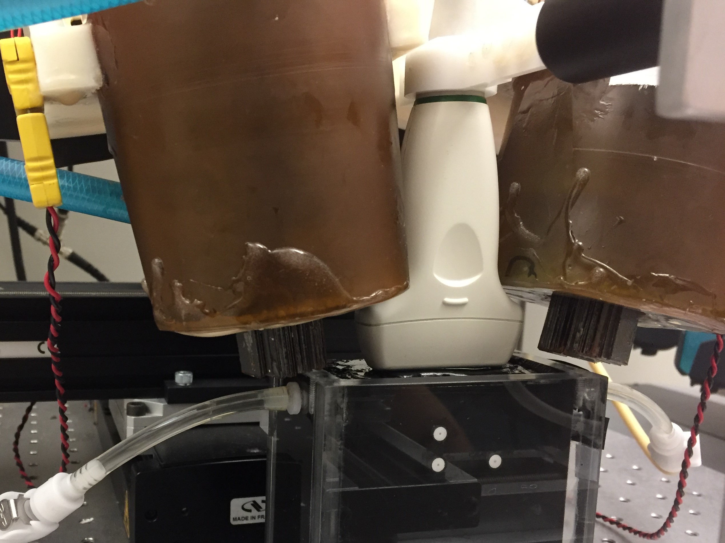
Figure 1: The MMUS system being used to image a gelatin human tissue-mimicking phantom. Note the large brown magnets on either side of the white transducer, and the black phantom below the transducer.
In order to create a magnetic field large enough to induce detectable oscillations in the iron oxide-labeled portions of the image, we use two large solenoids as electromagnets. The solenoid coils are driven with a square-root sinusoidal voltage waveform, which produces a magnetic force that varies sinusoidally in time at 2Hz. Water chilled below 8şC is pumped through a hollow cavity surrounding the coils, preventing the electromagnets from getting hot and melting. To enhance the strength of the magnets, metal cores made from sheets of grain-oriented electrical steel are inserted through the middle of the coils, and the poles are aligned in opposite directions, as shown in Figure 2. The magnetic force is further increased in the imaging area by positioning the magnets as close as possible to each other, and to the surface of the tissue sample, and by tilting the magnets 10ş from the vertical.
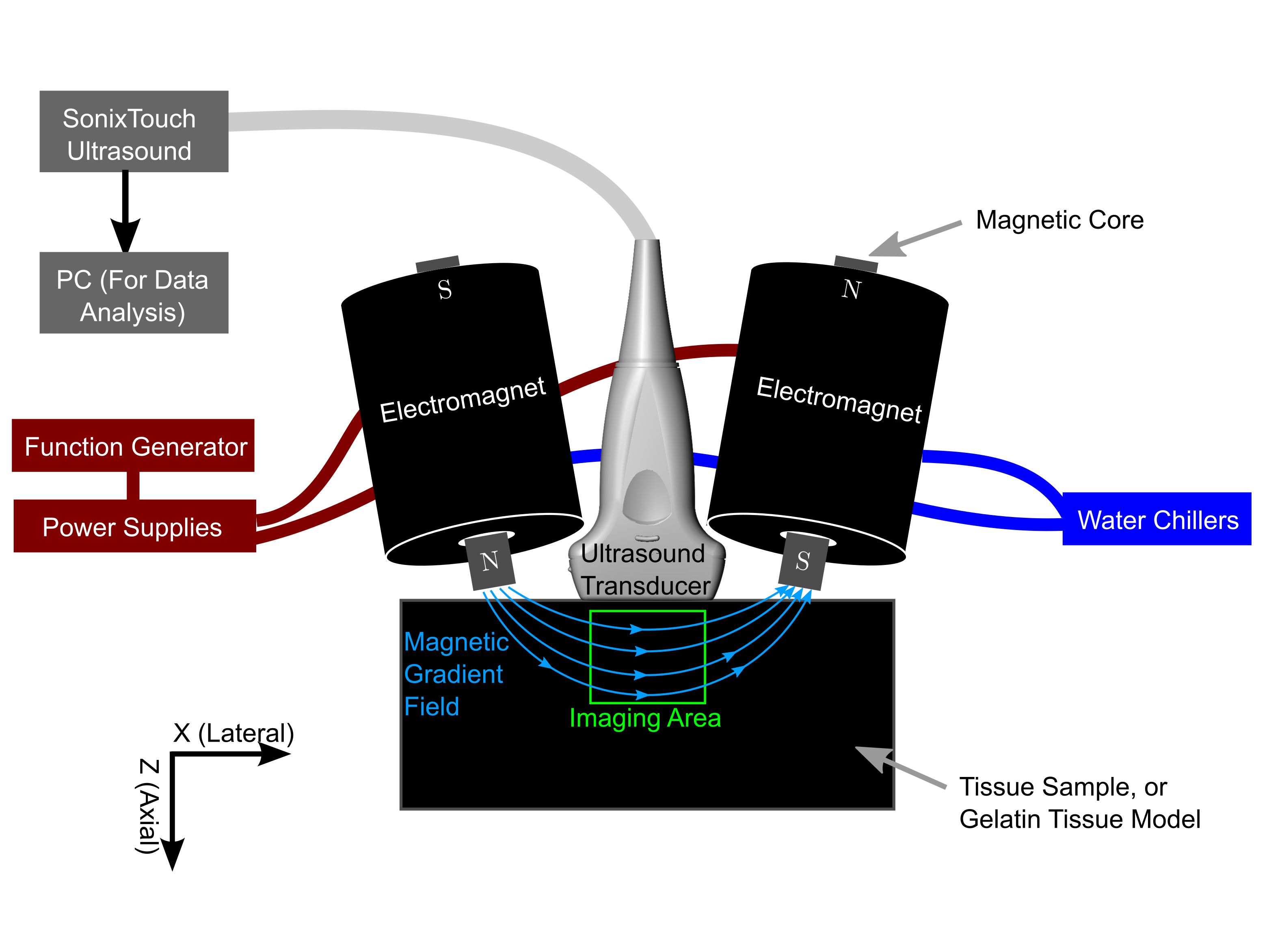
Figure 2: Schematic of the MMUS system. The function generator drives the power supplies with a square-root sinusoidal voltage, creating a magnetic gradient force via the electromagnets in the imaging area that varies sinusoidally in time. Water chillers keep the solenoid coils cool. Ultrasound RF data is collected and analyzed on a separate PC to determine the location of any iron oxide particles in the imaging area.
In our lab, we are working to use our MMUS system for detection of blood clots in arteries. We have recently published our work on MMUS in the presence of pulsatile flow in phantoms (Levy et al, 2018), with the eventual goal of detecting and sizing thrombosis. Our MMUS system was also used in a recent publication Hossain et al, 2018) which explored the ability of a novel blind source separation algorithm to reduce noise in MMUS images.
intro page - research - publications - people - open positions
UNC Physics & Astronomy - Biomedical Research Imaging Center - UNC Home